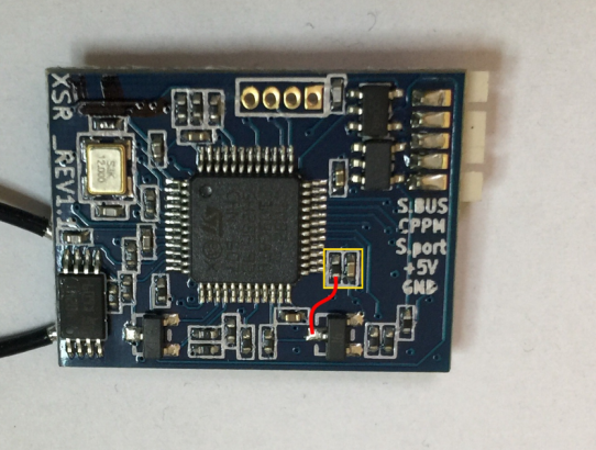
A while back I wrote about how to modify the XSR (aka X4RS) to get at the non-inverted smartport signal so as to work with the STM32 F1 and F4 based flight controllers (F3, and F7 have the ability to invert serial communications built in). Well this is part two of that modification. The original can be found here: https://blck.mn/2016/06/smartport-the-frsky-xsr-and-betaflight/. The idea came from a discussion with Andrey (@diehertz – developer of the BLHeli Configurator) about how to get the RSSI output from the X4RS to the CPPM pin. Given the CPPM remains unused for most – it makes a good candidate for re-purposing to other uses.
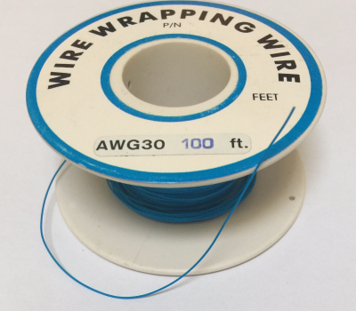
So if you do not have a need for CPPM output, you can make a very nice little modification that will give you both the inverted and non-inverted smart port capability. Using a small piece of wire and removing two components you can re-purpose the CPPM output as non-inverted smartport. I use motor wrapping wire for PCB modifications / fixes, but any link wire will do (it need not even be insulated if you are careful with placement). See below:
So the two components you must remove are a small resistor, and a capacitor. These two components are to current limit and filter the CPPM signal output. These components are located at the bottom of the board next to the STM32F1 micro controller. See image:
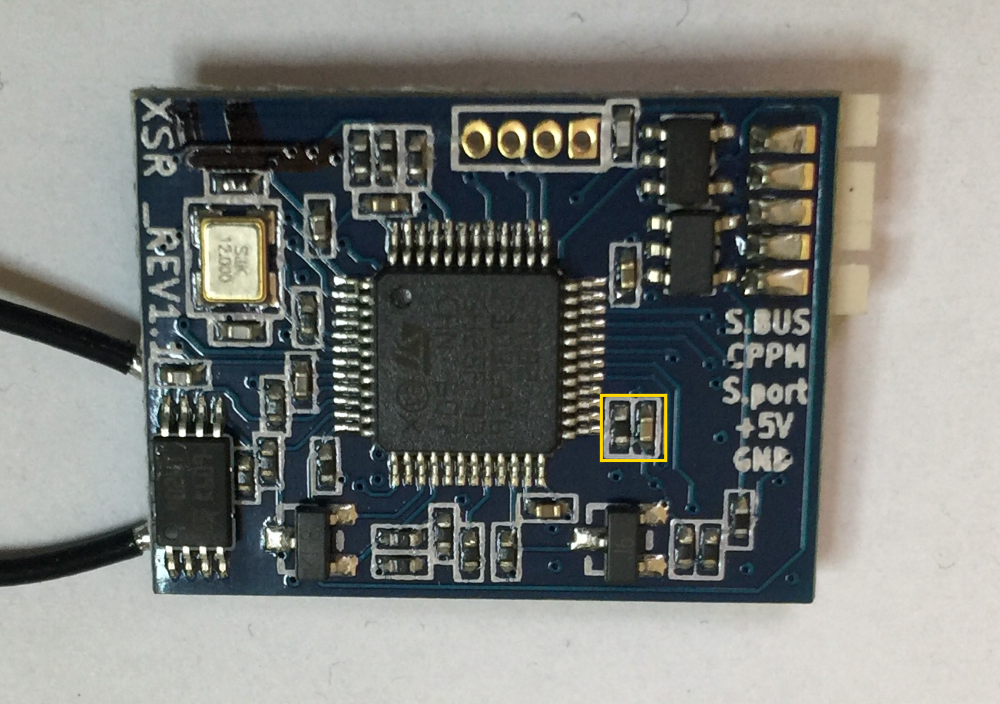
The easiest way to remove them, given their size is to wet a soldering iron, place the tip on top of the components and wait a few seconds and drag the tip slightly. The component should simply come away with the tip. There are plenty of instructional videos on how to remove small components so please check it out.
Once removed simply add a small link between the bare pad (or pads) towards the base of the board (oriented by the text). It does not matter which one you use either the cap or the resistor or both as they are connected together and are routed to the CPPM output on the JST connector.
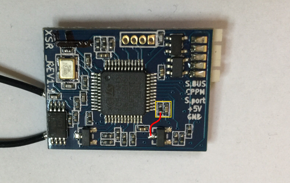
The other resistor pad (above where you solder the wire to) is connected to the bottom right corner pin on the MCU, and the other capacitor pad is connected to ground. It is very important that solder bridging to those other pads is NOT present. They must remain unconnected.
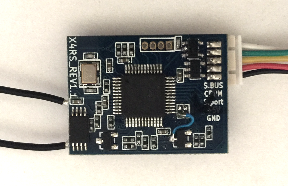
This modification will allow you to flick between inverted and non-inverted easily, and keeps the build clean as you can use the connector / cable supplied with the receiver. The CPPM wire (green if using the supplied harness from Frsky) from the connector is then connected to any free non-buffered UART TX pin on the F1 or F4 based flight controller.
NOTE: with this modification the yellow wire in the FrSky supplied harness is the inverted SPort connection, and the green wire (CPPM) will be the non-inverted.
