So we have talked about DSHOT a lot lately and so far it has proven to be quite the upstart. Whilst there are other options, such as CAN (Controller Area Network), here I will highlight the possibility of yet another digital protocol for ESC communications.
What is wrong with DSHOT?
Nothing really. There is of course the one major drawback of DSHOT. The massive DMA (Direct Memory Access) requirements of setting up the timer outputs. This use of DMA is needed for achieving the speed as the processor alone is not capable of delivering the IO transitions needed. The result of this is that some flight controllers are not able to take advantage of it due to DMA conflicts, or other options such as LED strips or black box logging need to be disabled if you want to utilise DSHOT.
Enter SPI
Most micro-controllers worth their weight include an integration option call SPI (Serial Peripheral Interface). This bus has proven highly versatile, being used for everything from its original intentions of inter-peripheral communications to being used for unexpected roles such as bit banging video signals for simple on screen displays. SPI is also extremely reliable and fast. The reason why it is used for example for communicating with Gyros on existing flight controllers.
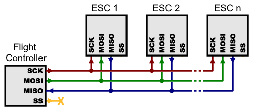
So how can SPI be used for an ESC. Normally SPI requires four (five if you include the ground) connections between a master (MCU) and a slave (e.g. GYRO). The first a slave select (SS), also known as chip select (CS). As multiple slaves can be on a SPI bus, a means by which to select a slave is needed. There is one such SS connection required per slave. Second requirement is a clock (CLK) signal. This indicates the transitions or bits on the data connections. The two remaining connections are data in to the master and out of the slave (MISO), and data out of the master and into the slave (MOSI). The final, and fifth connection, is a common ground.
For ESC communications you could get away with simply three connections. There is no need for the slave select as all ESCs would receive the same update frame, with individual motor speeds identified within the frame (or frames). The MISO is also not needed unless optional sensor data feedback is to be sent from the ESC. Thus you only need CLK, MOSI, and a ground as a minimum.

Each ESC would be connected to the same three wires in parallel (including ground) – so there is no need to chain the ESCs (like in CAN) or have multiple connections for each ESC.
So how fast?
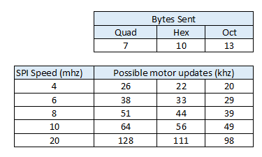
SPI is capable of varying speeds, specifications of the master and the slave will dictate actual speeds. The bus will allow speeds all the way to 20mhz (and possibly beyond). In theory this could allow up to 128khz motor updates at 20mhz SPI for a QUAD. Length of wire connections, noise in the system and other factors will all have an impact on the maximum possible speeds.
Here is a simple chart to indicate some of the speeds based on the protocol proposed below and an idle time between data frames of at least 100 CLK cycles.

The protocol
As with anything you actually need a protocol for transmitting a message between devices. This protocol has the advantage of SPI speed so can encapsulate so much more by giving a frame a type. So there are a considerable number of options and opportunities in the future for what the FC can send to the ESC (and back again).
As a start of course you need a data frame to indicate the speed of the motors. There are two main options, have a single frame per motor, and send each motor one after the other (with a motor address included in the frame).
Example 1:

The other option (preferred by me) is to send a single frame with each motor value already in the frame, and the position of the value in the frame indicates the motor address.
Example 2 (preferred):

There are advantages, and disadvantages to both – but the fact that a frame type is included means both options could actually be supported leaving the choice up to the user.
The ESC would need to be configured to respond to a particular address via some form of identification process, perhaps something similar to the binding of a radio receiver. Put it into binding mode, and then the binding command is sent from the FC, with the motor position to store. How could this be done? Quite easily in fact as a short process, as follows:
- The FC would be put into binding mode for a given ESC and continuously send a bind frame type, indicating the MOTOR address to be bound. This would be done in betaflight configurator or similar.
- The ESC that should accept this address would have its motor spun, say 5 revolutions, and the back EMF is picked up, and the address received from the FC is stored by the ESC.
- The ESC would give a visual (LED) or audible indicator (motor chirp) can be given to the user indicating completion.
- The process is started again with the next MOTOR address to be bound.
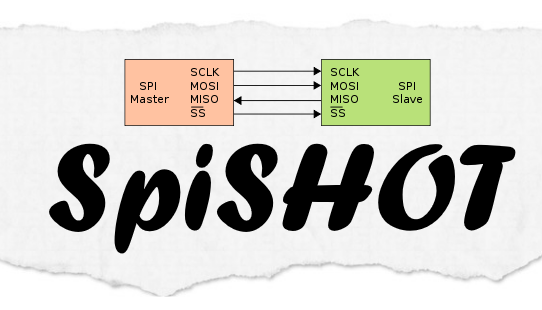
So what would you call such a protocol? Given it uses the SPI bus, and given everyone recognises the SHOT moniker it would be fitting to name it SpiSHOT.
So what?
Some of the benefits to using SPI of course is it is able to be done with minimal overhead on the MCU, using a single DMA channel.
The problem is that it is NOT backward compatible. The ESC hardware will need to expose a SPI port, and have the necessary firmware support it. It would be of particular benefit immediately in 4n1 ESCs as it is an instant reduction in connection count from five wires now, to the use of only three wires (four IF you want to include ESC sensor feedback – remember the MISO connection).
So whilst it is currently only theoretically possible. Hopefully some sample hardware will be completed within the next 3-4 weeks and we will be able to test this theory shortly.
.
